
By John Tingay, CTO at Paragraf
Electric vehicles (EVs) are becoming more popular as consumers get to know their mix of performance, comfort, and cost. However, many consumers are waiting until the range of EVs increases and their charging times decrease before making a switch. This blog will explore how better magnetic field sensing, enabled by Paragraf’s graphene Hall effect sensors, can help battery designers address these issues.
One challenge in designing better batteries is to characterise the effect of novel cell chemistries and shapes, the heating effects during charge and discharge cycles and the effect this has on battery life. The contribution from the distribution of current within the battery can only be inferred from other measurements or from intrusive interventions
External measurements of cell temperatures are possible, but there is a lag between when a cell’s temperature changes and when that change is sensed. A more direct way to measure current density is to measure localised magnetic fields, but conventional magnetic sensors lack the necessary field resolution and dynamic range. It is also more challenging to interpret geometrical interaction with the magnetic field.
Graphene’s 2D advantage
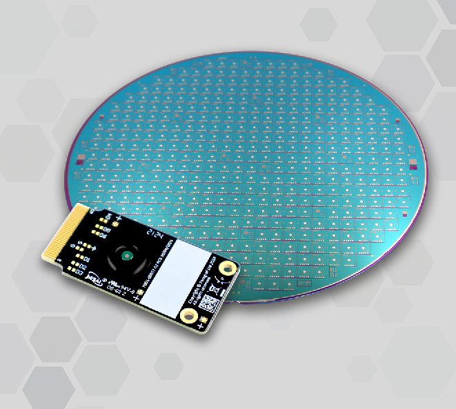
Paragraf’s expertise enables graphene deposition in one-atom-thick layers, and to optimise the resultant sensors for low-field environments and normal ambient temperatures. The sensors’ small size also enables good spatial resolution.
Paragraf’s GHS-A low-power, Hall sensor uses a single, one atom thick 2D layer of graphene. This only detects the component of the magnetic field perpendicular to the plane of the sensor, simplifying the analysis. The sensor has a high dynamic range and resolution better than 10ppm. It is also free of hysteresis effects. It produces an output voltage proportional to the magnetic field, with a linearity better than 0.2%.
Improving EV battery design
How does this help design better EV batteries? We think in various ways. For example, it will be possible to put our sensors beside a cell’s cathode and anode cell connections to sense absolute currents and changes in current flows, and hence derive insights into the way in which the cell’s internal resistance is changing.
Placing multiple GHS-A sensors on a cell will enable real-time recording and analysis of local variations in its internal current density, as well as revealing the directions in which currents are flowing. This will help map the ways current flows change during charge and discharge cycles. It will also make it easier to find hotspots that could lead to cell failures and, crucially, will help to identify them quicker than conventional temperature measurements otherwise would.
The Paragraf sensors will also be useful for quality assurance during cell manufacturing, checking that each cell meets its specification. At the end of the EV battery’s life, the sensors can be used to screen cells to reveal which should have a second life in, for example, a grid storage array, and which should be recycled.
To help battery designers explore the Paragraf GHS-A graphene Hall effect sensor’s capabilities, we have produced a starter kit.
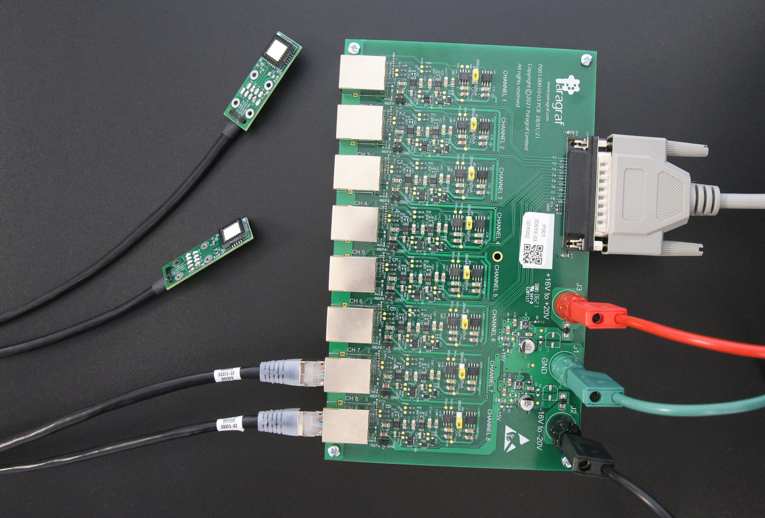
The GHS Array Starter Kit with connected GHS-A probes
The kit includes an eight-channel interface board and one GHS-A sensor probe. The probe board incorporates a temperature sensor to enable temperature correction of the Hall effect voltage measurements.
Graphene Hall effect sensors in use
WMG, a research, education and knowledge transfer department based at the University of Warwick, assessed the board and eight GHS-A sensor probes to instrument a test rig for pouch cells. Three sensors were connected close to the pouch terminal tabs, where the highest current density was expected, three at the cell’s centre and two at its far end.
The cells were tested by charging and discharging them in ten-second bursts. The image below shows the magnetic field measurements from the sensor at the cell’s cathode. The maximum field detected was approximately 700 µT when the pouch cell underwent a 160 A discharge test.
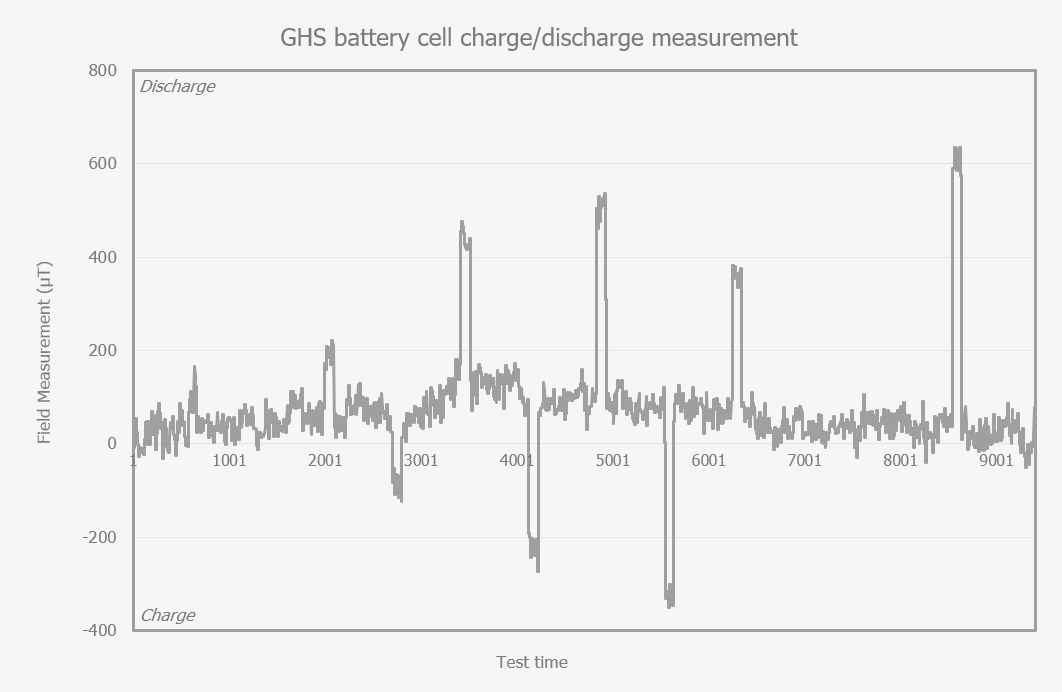
Magnetic field measurements from a sensor close to the cell’s cathode during charge and discharge cycles
The detected fields, and therefore the current densities, in the middle of the cell were lower than at the cathode, and at the far end of the cell, the measured magnetic fields changed much less.
This is a very direct demonstration of the way in which the sensors allow users to understand how current is distributed during fast charging, or the kind of heavy discharge needed to enable rapid acceleration in an EV. The image above also shows the responsiveness of the GHS-A sensor, which was easily able to track in real time the rapid rise in magnetic field strength corresponding to the 160 A discharge event.
Consumer interest in EVs is still limited by range anxiety and concerns about lengthy charging times. Battery cell manufacturers need to develop better cell chemistries and formats to overcome these concerns. The challenge in developing cell formats which allow fast charge/discharge is that these pose higher safety risks with increased risk of hotspot formation leading to thermal runaway and potential fire. This leads to the requirement for a better understanding and monitoring of cell behaviour. Paragraf’s GHS-A sensor can provide the kind of insights into internal current density distributions and flows necessary to do this.